Overview of the Protectli FW4B
Overview
This is continuation of my Protectli OPNsense Router Project series. Head over to Part 1 - Project Overview for a complete overview of the project.
Let’s look at the Protectli FW4B
- Intel® J3160
- 4 Ethernet ports
- 8GB RAM
- 32GB mSATA SSD
- 4G Internal LTE modem MDG100 (option from Protectli)
I like the Protectli line of hardware. It generally comes with everything you need to get going. The few times I’ve had to engage support they have been super responsive and very helpful.
In this particular build I encountered a bad LTE modem. Protectli support helped to get a replacement out quickly. I highly recommend a burn-in period of 72 hours before deployment to a remote site, for your own sanity.
Introduction to the Chassis
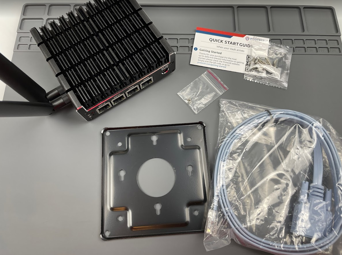
Shown is the mounting hardware, spare screws for LTE/SSD cards slots, serial cable, and the computer. Packaging also includes a 12v AC/DC power supply, not shown.
From left to right, power button, speaker/mic, USB-A, serial port, HDMI 1, HDMI 2.
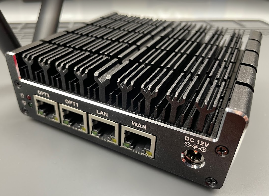
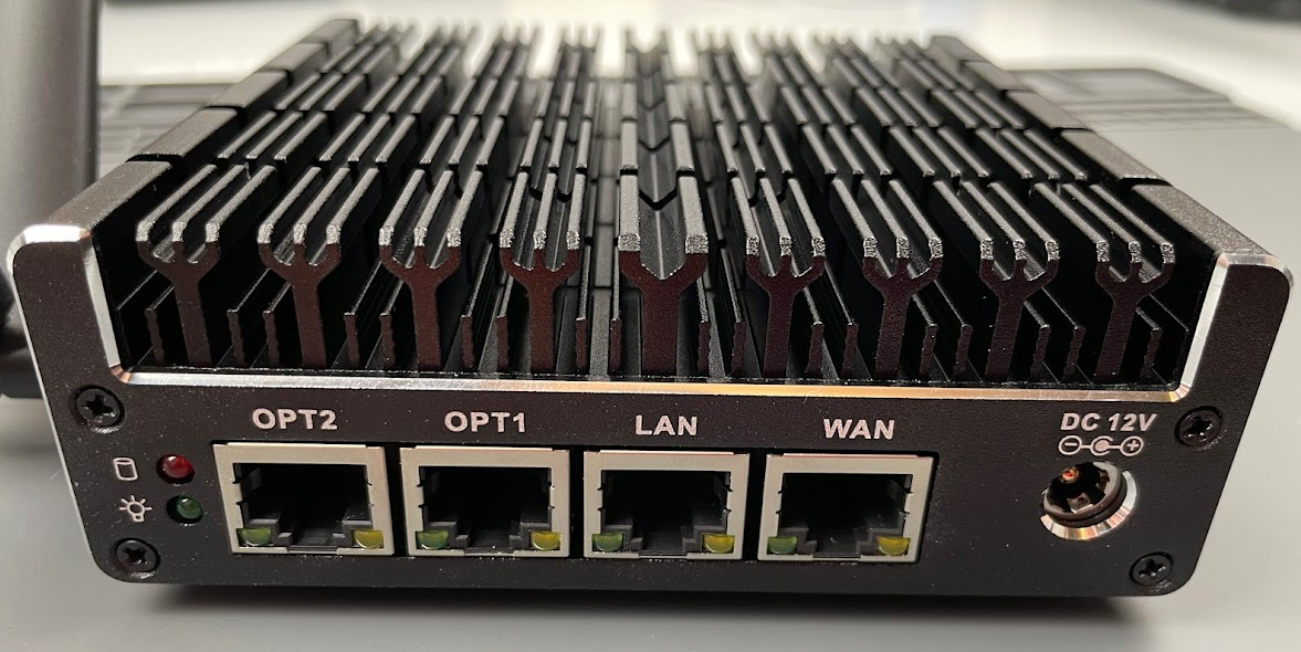
From left to right, hard drive activity (red), power (green), OPT 2 (Ethernet), OPT1 (Ethernet), LAN (Ethernet), WAN (Ethernet), 12v DC power in.
The four screw points around the label are for mounting to the optional rack mount shelf, or the provided wall mount bracket. To open the case, remove the four black screws on the outside near the rubber feet and pull the back plate up. It should be loose.
Caution:
The plate doesn’t have shielded screw holes for the VESA mount. Be sure to use the correct length screw or you might end up driving into your boards inside.
Internals
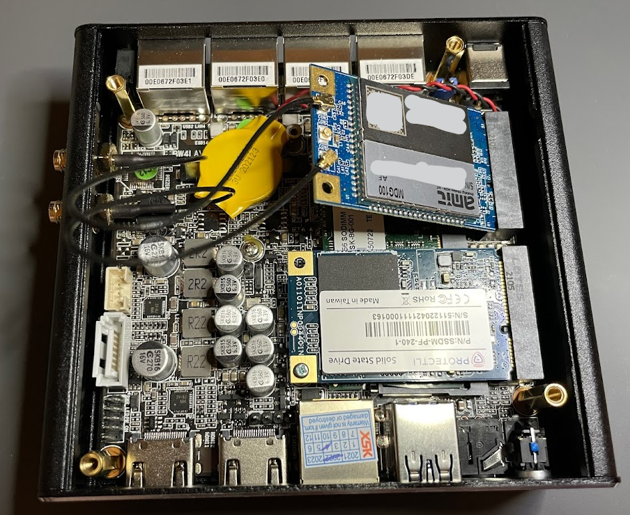
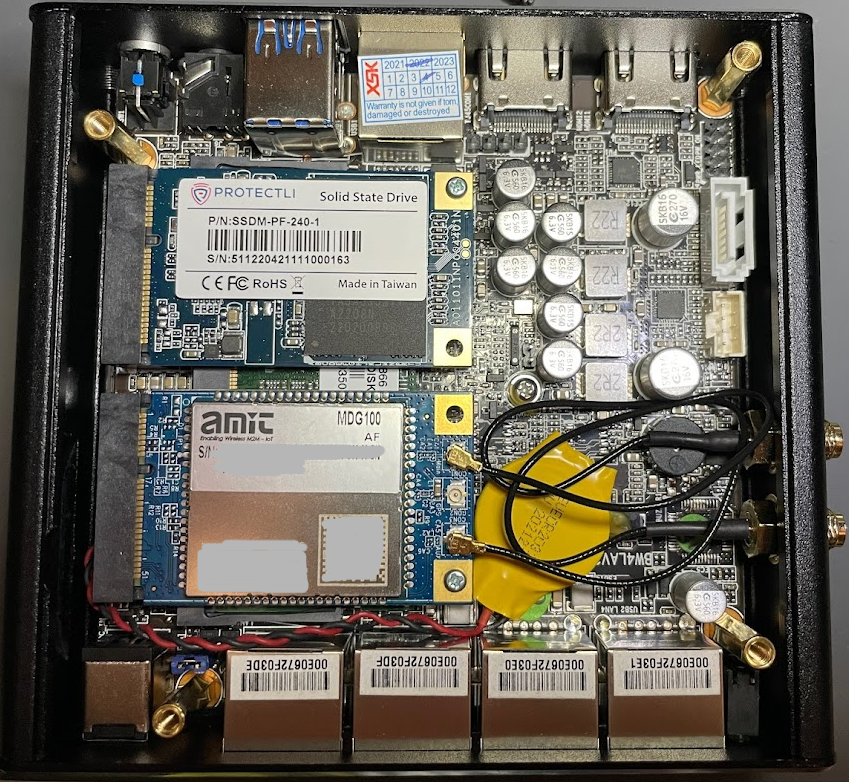 Some numbers hidden to protect the innocent.
The top left card is the 32GB SSD, and below that is the MDG100 LTE card, under these cards is 8GB of laptop RAM. At the bottom you see the 4 Ethernet ports. To the right side are the LTE antenna connectors.
| # | Description |
|---|---|
| 1 | System state after power loss jumper. Setting this will cause the system to power on after a power outage. |
| 2 | SATA power supply. |
| 3 | SATA data connector. |
| 4 | Front panel header. Power switch, reset, etc. |
| 5 | USB 2.0 header. |
| 6 | NVRAM reset. |
LTE Modem
This chassis can be ordered with either an LET modem or a Wi-Fi card. My application required LTE.
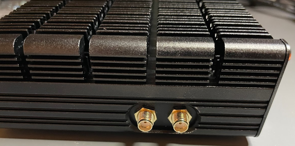
LTE antenna connectors without the antennas attached.
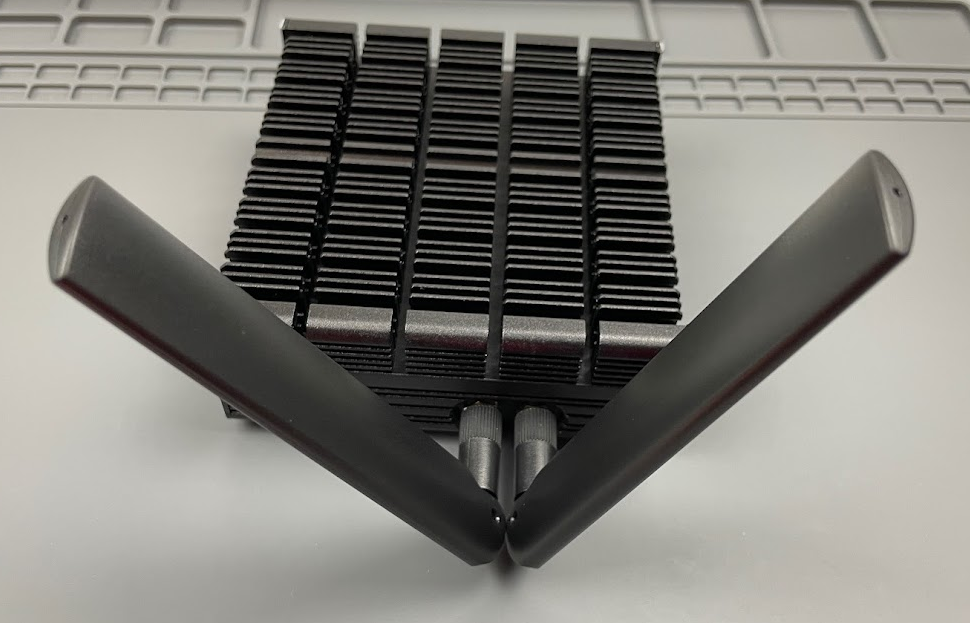
LTE antennas attached. The antennas appeared to work better in the position shown above - YMMV.
You need to remove the LTE modem to insert a SIM card. Simply remove the screw holding the modem in, allow the springs to pop it up, then slide out. To put the modem back in, insert it at the same angle, push down, screw it in. The antennas don’t need to be removed to change the SIM card.
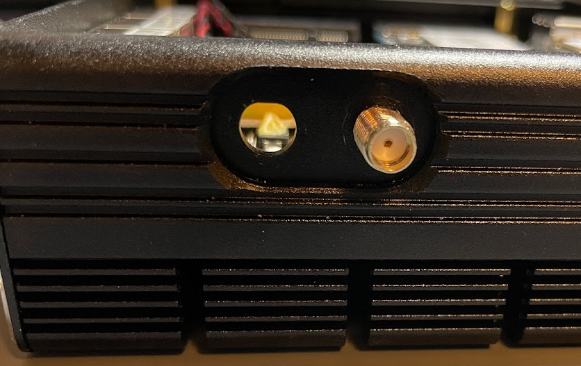
The antenna connectors are keyed to insert only one way and to prevent rotation.
The motherboard speaker is blocking our antenna removal. You can get past it, but it takes a bit to wiggle it out.
I’ve never designed a motherboard so I can’t begin to understand the complexity involved. Maybe making the speaker connectorized like the battery would have been a better route. You shouldn’t need to remove the antenna so this probably won’t be an issue for most users.
Head over to Part 3 - MDG100 LTE Modem




Comments powered by Disqus.